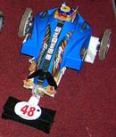
 A line follower robot is an autonomous mobile robot that can follow a path. The path can be a white pah on a black surface or a black path on a white surface. Line follower robots are usually entertainment hobby robots. However, they can be improved and used in industry in order to carry some loads on a definite path or in markets and cafes for similar purposes. A line follower robot is an autonomous mobile robot that can follow a path. The path can be a white pah on a black surface or a black path on a white surface. Line follower robots are usually entertainment hobby robots. However, they can be improved and used in industry in order to carry some loads on a definite path or in markets and cafes for similar purposes.
The important point of building a line follower robot is a good control that is sufficient to follow the path as fast as possible. The below diagram shows simply how a line follower robot works.
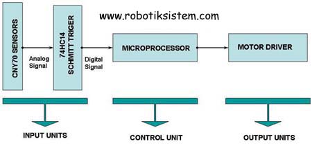
 INPUT UNITS: INPUT UNITS:
Input units consist of the sensors that detect the white path on black surface or the blakc path on white surface. QRD1114 IR reflective line/object sensor and CNY70 reflective optical sensor are the most commonly used sensors for line follower robots.
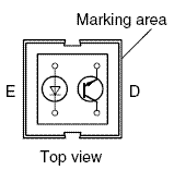 The CNY70 is a reflective sensor that includes an infrared emitter and phototransistor in a leaded package which blocks visible light. The CNY70 is a reflective sensor that includes an infrared emitter and phototransistor in a leaded package which blocks visible light.
The emitted IR of CNY70 reflects on the surface back to the phototransistor part and affects the base of the phototransistor. The black or white color of the IR reflection surface causes different analog signals on the output of CNY70. To convert the analog output signals of CNY70 into digital signals in order to transport them to the microprocessor, 74HC14 Schmitt Triger can be used. When CNY70 sensor detects white, the analog signal is 5 V and 74HC14 converts it into logic 1. When CNY70 sensor detects black, the analog signal is 0 V and 74HC14 converts it into logic 0.
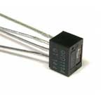 The QRD1113/14 reflective sensor consists of an infrared emitting diode and an NPN silicon photodarlington mounted side by side in a black plastic housing. The on-axis radiation of the emitter and the on-axis response of the detector are both perpendicular to the face of the QRD1113/14. The photodarlington responds to radiation emitted from the diode only when a reflective object or surface is in the field of view of the detector. The QRD1113/14 reflective sensor consists of an infrared emitting diode and an NPN silicon photodarlington mounted side by side in a black plastic housing. The on-axis radiation of the emitter and the on-axis response of the detector are both perpendicular to the face of the QRD1113/14. The photodarlington responds to radiation emitted from the diode only when a reflective object or surface is in the field of view of the detector.
  CONTROL UNIT : CONTROL UNIT :
The control unit is th microprocessor part of the robot. The microprocessor takes the input signals from the sensors, use them in its program and make decision of the next movement of the line follower robot to follow the path. The output signals are transfered to the motor driver parts of robot. The most commonly used microprocessors are the pic microprocessors produced by microchip.
 OUTPUT UNITS : OUTPUT UNITS :
For a line follower robot two dc geared motors are enough. The motor driver circuit can be prepared by using darlington transistor on a H bridge motor driver circuit or by using an integrated motor driver circuit like L293D or L298. The diagram shows the driving of the motors.
 ALGORITHM FOR LINE FOLLOWER ROBOTS: ALGORITHM FOR LINE FOLLOWER ROBOTS:
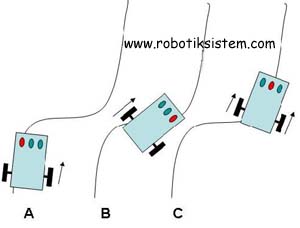
A simple line follower robot can be built by using three CNY70 sensor. The schematic picture of the line follower robot while it follows the path is given below.
|

